Custom Search

2010-08-12

Making the new Solera

Making the new Solera
(NB: I decide to bring this section out into a post by itself)
I am planning to build a guitar with a elevated fingerboard design, and thus the solera would need to be changed.
Anyway since I had plenty of MDF, I decided to make the solera out of the MDF
Though I had 1" thick MDF, it's very difficult to cut it.
So instead I glue 2 pieces of 1cm thick MDF together to form the main board.
And I cut a piece of upper bout out of cutoffs and use my block plane to plane it into a wedge.
The upper bout piece sloped down all the way to the waist.

Recently I just upgraded the block plane's iron to a IDC replacement which is a cryogentically treated A2 1/4" thick iron.
(In short a harder and able to hold an edge longer but also harder to sharpen)
The block plane now works like charm.
Even though I sharpened the original Stanley blade, the feel wasn't any good.
This is probably what they termed as plane iron chatter?

Finally, I use my compass plane to plane the dome and touch up using the sandpaper.
I didn't really use any curve stick to guide but rather's use my eye as the judge for the curvature.
It's a complex curve with a deepest portion of 5mm.
For the edge I use my Stanley block plane to remove the material and to smoothen out the curve.
Also I try to make the wedge portion transit smoothly into the dome depression and use a MuJingFang bullnose plane for that purpose.

I also got around to make the template out of 2mm acrylic sheet.
The plantilla I used is the Torres FE19 plantilla which I enlarged from the Romanllios book.
The size is slightly smaller than the previous Hauser plantilla which I used.

This time round I will coat the solera with a finish.
Inhaling too much of the MDF dust is really toxic.
Even with 2 layers, the solera also bends quite easily at the neck joint portion.
So I would need to reinforce the bottom with a piece of pine wood.

The idea of the raised fingerboard is actually to make the upper bout dipped down.
Thus the fingerboard portion would be exposed, making the access to the high frets easier.


The upper bout for the raised fingerboard portion


Removing the waste portion with my block plane


Can see wedge shape forming nicely


On the solera


Another view


The acrylic template showing the raised upper bout.
If you invert it the front upper bout would dipped down thus making the fingerboard "raised".


Side view.


Making the dome depression with my MuJingFang compass plane


Using the bullnose plane to make sure the curve from the raised upper bout transit smoothly into the doming depression


Using the block plane to smoothen the perimeter of the doming


All the tools used in the creation of the doming.
The MuJingFang compass plane and the Stanley block plane are really very useful.


The curvature of the topboard.


5 mm depression


The depression curve


Cutting the centre part for the neck. The centre cut out will be inserted when the neck isn't glued to the topboard yet.


Gluing the raised part to the solera


My solera after the raised upper bout is glued.


Closed up. I drew the outline of the plantilla to the solera


From the neck view


Clamping 2 piece of pine to get the correct width


Glue the pine to the solera to support it.


Now it's much stiffer


Added 2 wing pieces to stablise the solera
Drilled the center hole too.


Glue 2 pieces of plywood for the top piece of go-bar stand.
(I did spread the glue even)
They will be supported by 4 pieces of threaded rod.


Saw to fit using the ryoba


Varnished the solera with the Ronseal quick dry varnish
Next to come is to drill the holes for the supporting blocks and make those supporting blocks.

After a long dilemma, I finally decide to make the side support.
But not blocks but rather a full side frame mould.
Sawing the pieces is really a hard job especially since I don't have a bandsaw.
I had to do it by a jigsaw.
The trimning part will be done by my trimmer with a trimmer bit.
Well one of the reasons why I didn't do a block is because I hate to cut the slots onto the beautiful solera ...
Sometimes it's better not to make a good looking jig...

After vigorous saw of the individual piece using the Jigsaw, it's really tiring.
Next to come will be trimming the individual pieces to the template using a trimming bit.
That will be another noise generator but because I cut quite closely to the line the dust and noise generated should be minimum.
Before that I should be drilling some registration holes to align the pieces together.
Stay tune...

I continue with the side mold. Drilling those registration hole did not seems to be that easy.
In the end when stack up some of them didn't align properly..
I had to do some trimming again.
I did the trimming of the main pieces with the template using a trimming bit.
Then I proceed to glue the spacer block to the 3 main pieces.
After they dried sufficiently I drill those registration hole thru' the space block and then finally bolt up all the assembly.
I had to re-drill the reg hole again thru' the assembly as they didn't align properly.
After bolting up I resurface the protruding area and glue them up.

Next to come is to drill those holes into the solera and install some T-nut for holding down the side mold to the solera.
Well I need to find some bolts that is so long...

The side mould, not yet trim and glued
How the side mould would look on the solera

The side mould

Another view

Ready to do the trimming with the trimming bit.

Triming in action

Glue the center spacer block 
Well a cheap way to gain more height and also to make the side mould lighter

Glue up

The complete side mould

Trimming the spacer block.
The side mould trimmed to size

Drilling the holes onto the solera

Another view


Drilling thru' after marking.


Realigning the holes after drilling thru' Without a drill press it's very hard to drill with precision.
Now to find long enough screws to fasten to the solera

Now I need to make the bridge caul to press down the top into the doming of the solera
and also the part to hold the upper bout.

For the caul, I made it from the spare pine wood which I obtain from IKEA.
I trace the curvature form the solera and plane it accordingly
After that I simply drill the hole for the central part.

The caul held by the central part

The caul tracing the doming in the solera

After drilling the hole.

2010-08-11

Jointing the Top

Jointing the top
Well it's been a while since my last post and I have cleaning up my work bench.
Done up a rack for storing all my tools and woods but haven't sticker the woods in place yet.

Finally I choose a day where there was no rain to do the top plate jointing.
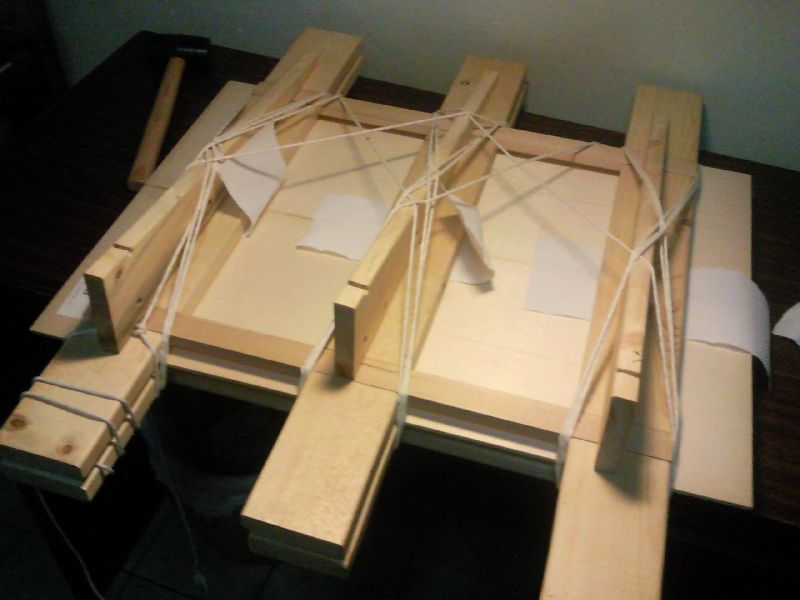
Using the same was as the back, I shoot the top and prepare to do the jointing using HHG (hot hide glue).

I prepare all the thing that I need and heat up the HHG (prepared previously)
  • Top plates
  • Jointing Jig / wedges
  • HHG with baby food warmer
  • Glue brush
  • Rope
  • Mallet for hammering in the wedges
  • Hygrometer


So I started the jointing process and with HHG I had to work fast (so no pics...)
I first laid the paper towel (to be scrapped /planed away after jointing).
Making sure the edge is the correct edge, I proceed to apply the HHG to the wood
and lay the wood on the bottom part of the jig.
Then I covered it with the top with some more paper towel and the top part of the jig
and started to tie them up.
Finally using the mallet I hammer in the wedges to tighten up the joint.
All in all it took me just less than 5 minutes to assemble the joint.
Then I proceed to clean up excess glue using some warm water.


Preparing the necessary materials / jigs / tools


HHG


Glue join and tie them up


Hammer the wedge to get a tighter joint


The joint close up view


After the next day, I remove the wedges and ropes.
When I wait for the glues to settle, I blew the dehumidifier at the top driving the RH down to 45%.


Removing the wedge and loosening the ropes


The top jointed


Looks good


The whole top

Jointing the back
I joint the back too the same way I joint the top.
But this time round I managed to find some wax paper.
It's actually the backing for stickers.
When I remove the strings, the paper didn't stick to the back at all.
The back's joint seam is not as good as the top, but luckily there will be a reinforcement strip (behind) and a backstrip inlay (front) in the middle seam.


Preparing the glue. The wax paper in place


All glued up, the dehumidifier driving the RH to about 43%


Glued back


The glued back with the plantilla drawn


Top and back

2010-07-05

Neck Making

#3 Neck Making: V-joint
I was busy making lots of jigs and mould recently so haven't really got time to post any pictures.

Anyway I started on another neck for my #3 guitar though I haven't decide on the back and sides material.
I am thinking of a cypress with an Torres FE17 plantilla.

After seeing many people making a neck with a Romanillos V-joint (mortise and tenon), I decide to attempt it.
There are lots of valuable resource on the forum which I participated

  • Covered/Fussen V-joint (Hauser) by David Schramm (A luthier who build great Smallman style guitars and did his research on Hauser guitars) on the Delcamp forum

  • V-joint tutorial by Waddy Thomson (An amateur luthier who build in the Romanillos style) on the OLF

  • V-joint tutorial by Joshua French (A Houston-based luthier who builds in the Romanillos / Torres style with Tornavoz) on the OLF

These great resources helped me a lot on how to build a V-joint.
So I did just that.

The scribing and sawing part was easy but the fitting part was tedious.
In the end I had to saw away the 1st V tenon i did and redo it again.

Here are my steps:

Marking the head angle 9 degrees (as per David Schramm). I choose a lesser head angle than my scarf joint is because my neck black was just about 1" thick.
If I choose a steeper angle I would need a thicke neck blank.


Making the triangle 1st with pencil.
After that I went through the making with a scribing knife.


The side view. You can see the 9 degree angle on the V.

Then I use my 1" paring chisel to chisel the marking to make it more prominent and easier to saw.


Using the chisel to make the marking more prominent


Fully scribed, ready to saw.

Then I proceed to saw away the wasted area.
I use a douzuki saw (Japanased backed pull saw) to do the job as it has very thin kerf and is able to saw in a straight line.


Sawing the wasted area


From the top end


Sawn V tenon


Another view


Side view

Then I proceed to clean the sawn area.
This is where I failed, in the end the V tenon's angle all got messed up.
I reviewed David Schramm's video on how he did the clean up and follow his method.
I planed the angle into the front face of the tenon and put a 90 degree wood to serve as an reference to clean up the V tenon.


Checking the head angle


Then I use the same face to draw the mortise part and saw the mortise on the head blank.

Saw away the mortise part. Note my sharpened chisel, the mirror surface.

After than I proceed to fit the V-joint this is the most taxing part.
I am using hide glue and to glue well the joint must not have any gaps.
Hide glues doesn't glue well when there are gaps.


The mortise and the tenon


The fitted V-joint (still need to plane the head part to correct thickness)


From behind view


I use the shooting board (one of few jigs that I am making) to remove the end grain during the fitting process


Jig makinng: plate jointing jig
I spend my time making some jigs.
Here's the story.
When I want to glue the head plate for my #2 neck, I found that I need to join the back first and use the cutoff for the head plate.
So before I can join up the backs, I need a shooting board and a plate jointing jig.
So I made this plate jointing jig based on the LMI jig.


The plate jointing jig


The top on the bottom part of the jig.
A top plate would cover the 2 plates and a rope is use to pull the 2 plates together.
Then the wedge would be inserted to exert more pressure on the 2 plates.

Shooting Board and Preparing the back for Jointing

Well I made a shooting board for shooting and jointing.
And then I began to prepare the backs for jointing.
Using my 16" MuJingFang wooden plane with a sharpened blade I began to even out the edges.
At first I apply the clamp the the 2 boards but in the end I discover as I need to take out often to do a light thru' check, I just simply hold it in place using hand.
There is a stopper block at the end of the shooting board.

When I do a light thru' check, I hold the pieces up against my table lamp and check which part of the 2 boards emits the light.
Then I shoot more of the touching areas (no light area) and even out the gaps.
I stop when I don't see any light thru'
It's really a great learning experience.
Next to come will be joining the 2 backs together but due to the weather (raining)
I decide to leave it for next time. (When it's raining the RH will be too high)


The shooting board and the 16" MuJingFang plane and the IRW backs


The shooting board and the 16" MuJingFang plane


Shooting


Holding with the left hand


Holding up the piece against the light to check for joint closeness


The 2 back pieces ready for jointing