Custom Search
Showing posts with label Struts. Show all posts

2008-02-01

The Traverse Bar

It was a fruitful day.
I managed to completed gluing all the top's struts including the harmonic bars.

Carving the enclosing struts
First of all I carved the enclosing struts to shape.
I think my chisel skill is getting better and better.
I noticed the chisel getting a bit blunt from all the carving.
I'd better be starting to look for a honing guide soon.

Carving the enclosing struts.


Completed carving


Top down view


The lower traverse bar
For the traverse bars or harmonic bars, I start to mark out the windows that I am supposed to cut.
For a moment I was think whether to do it like Torres which was basically an arched window or some other open brace design.
In the end I opt for a simple rounded corner rectangle.
It was pretty easy process to carve out the window.
Next I used file to smooth the jagged edges.

Marking out the window


Drilling the hole


Sawing the window


Both window sawn


Test fitting the lower traverse bar


The upper traverse bar
For the upper traverse bar, I was think whether to make it a open or close.
Torres' upper traverse bar was close and thus his upper struts could made an angle with the outer fan struts.
In the end I decided to make the upper traverse bar open.
In order to support the upper bout, the upper struts was made straight instead of an angle.
For the making of the upper struts (no pictures), I plane it to shape for the cross-section and taper the ends before gluing the struts.
It's definitely much easier to do it with plane then chisel.

Both upper and lower traverse bar sawn


Close up view. (Noticed the straight upper struts)


Oblique view


From the other side. The upper window has been smoothened.


Side view


Yet another view


Test fitting with the sides. The traverse bar has been trim at the ends


The gluing process
It's time to glue the struts.
The upper struts are glued using all the F-clamps.
The traverse bars are clamp using the F-clamps at the ends and in the center is the good old center screw.
The screw was abit short and I had to cut 2 notch in the center MDF strip to lower down the thickness.
The notch served to stablise the traverse bar too.

Gluing the upper struts


Gluing assembly


Low angle view


High angle view


I thought I would post some more photos of the completed braced top.

I try to fit the side to the top, but discover have to trim the harmonic braces more in order to accomodate the sides.
Using a mini hacksaw and then chisel I manage to trim the braces.
Now the side fit in the top better, though the upper bout curve still need a bit of adjustment by heat pipe.


Here's another view


A closer view of the braced top

2008-01-24

Gluing the struts

Preparing the struts
During the last 2 or 3 weeks, there happened to be pockets of free time available and so I worked on the guitar.

First of all, I resaw some of the struts to make more square especially the gluing surface.
Subsequently, I draw the struts layout on the top board itself basing the on the Torres fan design.
The fan struts had a focal point some where in the 15th fret region.
Most design of fan struts are in the 12th fret region but Torres' fan focal point is 52mm into the body and the outer fan will make a right angle (90 degress) with the enclosing struts.
All the information is from the Romanillos's book on the life the of Torres.

Then I saw the the struts to size according to the layout.

Here is the final layout


Another view.


Gluing of struts
Then comes the problem of how to clamp the struts while gluing down.
What to use to hold the struts in place while gluing?
As discussed previously I decide to go for the bamboo go bar method.

However, the bamboo gobar is not usable.
As the bamboo's thickness is not uniform, the go bar produced had varying strength.
So I gave up that method.
I contrived several other methods but to none seem to satisfy the need to press the struts into the depression.
In the end I discover that the set of Aluminium bars which I purchased for making the Cam clamps, had a potential to become a go-bar instead.
When I tried it, it was very successful.
So I decided to go with this method.

Due to time constraint I did not build the go-bar deck but use the underside of the table top instead.
However I soon to discover that the I need heavy weights to hold the whole thing in place as the go-bar was pushing the table up.
So building a go-bar will be next on my to-do list.

Here is the top board with the markings and ready for gluing


Gluing of struts


Another view: Note the doming especially for the centre struts


Close up view


All the struts in place.
The outer struts was using F-clamp due to lack of Aluminium bars and also the upward force exerted on the table top was too great.
Now I know why they use go bar deck instead of a simple table top.


Front view


Weights to keep the table down (mainly books)


Here is the topboard after the main fan struts are glued


The doming effect in the topboard


Carving the struts
The next day, I removed the struts from the go-bars.
I am pleased with the results considering its my first attempt in gluing using the go-bar.
Some struts slided on the surface thus dirtying the topboard.

Next I proceed to carving the struts.
At first I was using the finger plane but the length of the small plane was slightly too long considering that the struts was domed.
So I end up using the broad chisel I got from Daisol instead.
The chisel wasn't really that sharp and so I had quite a bit of hard time trying to carve the struts.
Due to some carelessness I accidently scratched the topboard with the edge of the chisel while carving the struts.
I was deciding between shaping the struts round or triangular.
At first I went for triangular but in the end I end up with round as round is the easier of the 2 to make it look nice.
The final shaping was using sandpaper to smooth the roundness.

Factors to consider when carving a struts
- Sharpness of chisel
- Protecting the top board while carving.

Luckily I did not glue the enclosing the struts because when I taper the ends I always over shoot the chisel.
If the enclosing struts were there, they'd sure be damaged...

Carving the struts


Tapering the end of the struts


The struts after carving


Another view


The full fan struts with the traverse bars (not glued yet) and the enclosing struts


Gluing the soundhole reinforcement and the enclosing fan struts

Next I proceed to glue the enclosing fan struts and the sound hole reinforcement
The sound hole is a weakness in the topboard and thus requiring the strengthening strip.
Some design like Hauser just simply have 2 vertical strips around the both sides and the top and bottom is strengthened by the traverse bars.
But I preferred a ring design and so used a ring instead.
For clamping down the reiniforcement I simply used the screw (which was used to secure the whole top board in place)
As for the enclosing struts, I used F-clamps and the Ibex bridge clamp (longer reach).
The planes are simply there to counter balance the lopsided weights at the enclosing struts end with all the F-clamp in place.
If not the whole board will toppled off the table top...

The process of gluing


Another view


Close up

2007-04-27

Sawing the struts

Til date, I have just started the guitar making process for 3 session.
Here are the details:

Session 1

I bought some tools from Daiso at $2 each.
It is really a good place to get cheap and good tools.
(They do sell alot of other good stuff but that's another story...)
- F-clamps
- Chisels
- Scrap woods (bass wood)

I started the guitar making process by sawing the struts from the block of spruce.
Using coping saw to saw the spruce block is not an easy task; it is very easy to deviate from straight line.
So to cope with that, I deliberately increase the thickness of the marking for at least another 50% or so.
(It is bound to happen actually, so got to think of ways to recover from the mistake.)
This is to leave enough margin for mistakes.
E.g. I need 6 mm thickness I would marked the line at 1.5 cm or so.
The difference would be removed by planing.
At the end of the session I have sawn quite number of struts, but still a long way to go...

One of the important points to take note is that, after sawing the brace, ensure that the surface is flattened by planing it.
This has to be done before you start to saw the next brace from the spruce block.
If this is not done properly, you could end up with a crooked struts.
Unfortuately, some of the struts which I have sawn, exhibit this mistake...


Session 2
In order to alleviate some of the hand and back pains I experience while sawing the struts, I bought a electric Jig Saw.
I bought it at AMK NTUC Extra which cost about SGD40.
Unfortunately after trying to use it for sawing the struts, the result was not what I had expected and very unsatisfactory.
If you think using the coping saw was hard, using Jig Saw was even harder,
especially in controlling it to saw in a straight line.
As a result, regretably, I wasted quite a bit of the spruce block :(
(Luckily I ordered 2 more spruce block, knowing that I would make stupid mistake here and there.)

According to my more experienced friend EJ, who has dabbled quite a fair bit in this art of luthiery, in order to make the Jig Saw cut in a straight line properly, you need a fence guide.
I was thinking of making a mold or something to achieve that.
One of the way is to fix the Jig Saw on a mounting block and use it like a Band Saw.
If that is the case, the the fence guide would simply be another removeable plank hold in place using the F-clamps.
However, making the mount could take some time and effort and my little work bench wouldn't have enough space to hold the mount either.
You need a proper size workbench instead.


Session 3
I have just bought a new digital camera (Ricoh R6) to take some pictures of the guitar making process.
All the pictures shown was actually taken during this session.
I merely backdate it.

I bought some more new tools from Daiso:
- Japanese carpenter saw
- Mallet (for hammering in the frets)
- Clips for clipping the kerfing
- Some screws and nuts (for making the mounts)
- Cork sheets for protecting the wood surface during clamping.

I also bought some tools at Art Friend:
- Adjustable carpenter square (for ensuring perfect straight and perpendicular edges)
- 1 metre rule (for measuring the string course length 650 mm)
- Some more bass wood for scraps


Here is a picture of my mini work bench and tools.
Top to bottom:
- Coping saw
- Adjustable Carpenter Square
- Japanese Carpenter saw
- Plane
- F-clamp


Sawing the brace:


Planing the block before sawing the next brace (Note the F-Clamp at the end to faciliate planing)


After sawing all the braces for the tops, I laid them out on the spruce top board.
Finally I can see the light after labouring for so long...
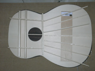

Here's another view


Bracing design

Explanation about the struts
The topboard is the most important part of the guitar
To support the string tension the topboard would have to be very thick.
However a thick top would not make a good sound and probably hardly any volume at all.
So in order to support a thin top (typically 2-3mm thick), struts of bracing have to be added to the top board to support the pull of the string.
The struts are laid in a pattern known as the fan struts; they fan out towards the lower part of the guitar.
It was developed by the Spanish Luthier Antonio de Torres.
Newer patterns include the modern lattice patterns which has a grid of cris cross struts


What I have in mind for bracing the topboard is something like the Romanillos's bracing pattern.
The upper and lower harmonic brace surrounding the sound hole, would be both open harmonic brace.
(I.e. the struts from the lower bout of the top board can / will extend all the way into the upper bout of the guitar.)
There is open slot for the struts to go through.
You can see some examples of open harmonic bracing at the following site:
- Romanillos Guitar Making Course
- Luthier Jeffrey Elliot's open harmonic bracing


My luthier friend EJ commented that the brace was too thick, so I am going to trim them down further.
Probably I will let the height of the bracing remain at 5 - 6mm, higher than normal height (3 - 4 mm).
After I have strung the guitar up during the final phrase, then I will fine tune the brace height either through the sound hole or an access hole at the end block.