
20131125
Actually once the box is assembled, technically speaking the rest is to prepare the box for closing.
Well it's just matter of how the stages / actions are defined.
In order to close the box I need to do the following:
1) Trim and shape the rim (sides)
2) Prepare back brace
3) Glue in side struts
4) Glue the back lining
5) Reshape the back profile with the back struts in place.
6) Inlay back strip
7) Thickness back
8) Glue brace to back
9) Close the box
So basically right now I am at step 3 of this stage.
I have trimmed down the sides to the correct depth around 100mm or so.
Usually I use a slightly deeper body to get a deeper air resonance.
This is especially so for my elevated fingerboard guitars.
The upper bout is shallower because of the elevation so I need to compensate for the volume loss by having a deeper sides overall.
This guitar is normal guitar without the elevated fingerboard so I need not go so deep.
Still the depth is about 105 or so.
With the back on it'll probably be nearer to 107 mm or so which is pretty deep.
I cut up the back struts and shape them accordingly.
Well these aren't the final height yet.
I will shape them after it's glued to the back and check the weight of the back (with brace) and the free plate resonance.
Anyway after the sides is shaped, I prepare the side struts and started to glue them onto the sides.
Originally I was thinking of using ABW for the side struts but after feeling how light the entire body is I decide to use spruce instead.
It will maintain the overall light body feeling which I am quite fond of, although it has not much bearing on the sound in general.

Shoot the curvature onto the back brace

Check with the template. The curvature was drawn from the template.

Can see the curvature more clearly.

Taper the ends. Saw first then shape with file.

3 back brace done and saw to size.

Side struts all prepapred.

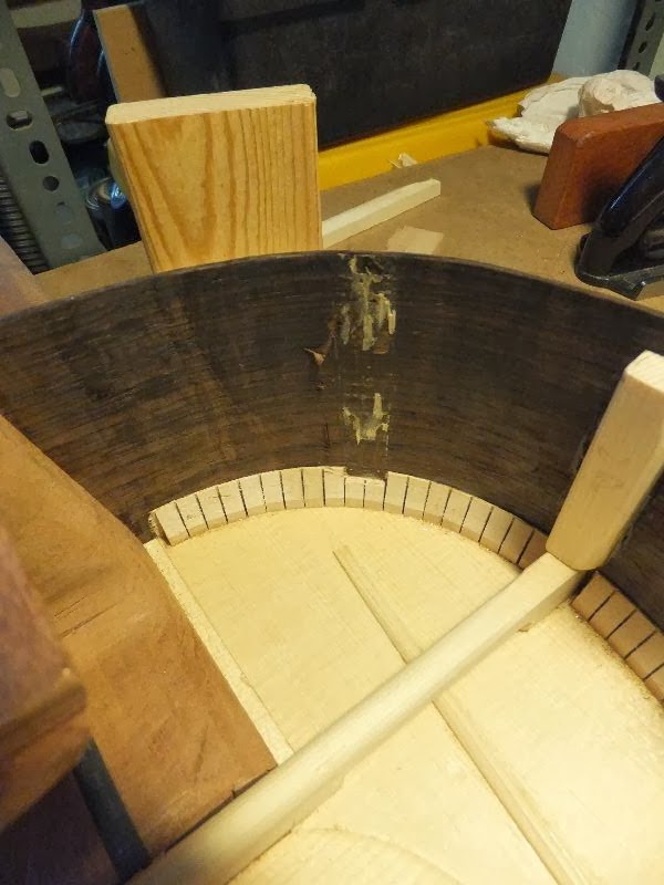
Cut the notch in the lining. The side struts must inlet into the lining instead of butting against it to prevent crack.

Before applying the hide glue.

Glue and clamped

Checking the back brace height on the side struts for the back brace. The 2 side struts for the UTB and LTB will be similar and they act as support for the traverse braces.
20131128
I prepare the rest of the side struts including the 2 pillar support for the UTB and LTB and the 1st 2 back brace.
Since #3 I always aligned the 1st 2 back brace with the UTB and LTB respectively.
For the 1st back brace I strengthen the structure by supporting it with the Spanish foot.
The upper bout is very a rigid structure as a result.
After preparing all the side braces it began to rain so I leave the gluing to another day.

All side braces prepared.

The 1st back brace with a notch embedded into the foot.

Close up view

Side struts all glued
20131212
It's been quite a hell of a week last week.
My younger son was hospitalized due to a new RSV (respiratory syncytial virus) Metapneumovirus
He was warded for 9 days.
The virus was very potent causing him to have pneumonia, bronchitis and high fever.
At the present, there was no known cure for it, all they do is to treat the individual symptoms accordingly.
So I didn't have any progress then.
Well anyway I also have a broken rib bone so I won't be doing any strenuous wood working stuff like planing.
More updates coming stay tune.
20131217
It's been quite a quite since I did any guitar making.
Not that I have any choice.
Anyway as I mention earlier I had been busy and now am not in good state to do any rigorous work.
I proceed to glue up the back lining
I just cut the reversed kerfed lining to size and glue them up.
As the sides are separated by the side struts, the lining is glued in short strips which leaves me plenty of time to glue it right.
The lining is held tight by clips.
Anyway I forgot about the space for side port which my friend has decided to add in last minute.
The first side strut is in the way.
After numerous attempt to heat it and wet it with warm water, the side struts didn't budge at all...
Damn who says hide glue is no good with water and heat.
It takes tremendous amount of both to remove it, which I am not going to try.
So I just chisel the side struts off and glue in the lining 1st.
That will be a patch for the side port so that part is pretty strong so resist any crack anyway.
So the back rim is done.

Ready to glue the lining

Starting to glue the lining

Chiseling away the side struts after failing to remove by heat and water. Hide glue is very strong contrary to what people say that it's susceptible to heat and water
Side strut removed

All glued
20131219
After the glue dried I began to trim down the lining and at the same time check for the smooth curvature of the back.
Other than planing the angle into the lining I also adjusted the back struts' curvature.
Once this is done the back would be ready to be go on.

Lining done

View from the top

Now I make it a point for the 1st 2 back struts to coincide with the LTB and UTB

Looks nice rite? :)

Planing down the lining. Usually the lining is glued about 1mm proud of the sides. This is so because the back is not flat at the rims but at an angle

Adjusting the 1st back struts

You can see the smooth curvature of the back struts
20140108
Well a happy new year to everyone.
I was stuck for this build for a while I had to wait for the arrival of new purfling.
So meanwhile I do whatever I can do.
I glued up the backing veneers for the sound port.
The sound port will be of a different shape from my previous sound port as the owner request a special shape.
This will be a challenge as there are purfling surrounding the soundport.
For that part I am still thinking how to achieve the nice shape...
Anyway I glued up the backing with BRW veneer
Normally I will be using spruce as a backing but the owner prefer a same color for the backing.
I glued on 5 layers with 2 cross grain and 3 along grain (with sides)
The glue used is my standard hide glue.

Preparing the backing veneer

Apply glue to the veneer

Intermediate clamp to hold the veneer in place

Final clamping once all the veneer are glued.
20140127
Well I had some time to patch up the lining for the back struts closing up the gaps.
Not only it looks better, together with bindings the air tightness of the seal of the body will also be better.
This leads to lower air resonance.
Glue in more lining to fill up the gaps in the slots for the back braces.


Same here

Same here.

Patching the lower bout. Now all the brace pocket are done. Next will be the sound port.
20130128
I had a discussion with the owner and we came up with this design of the sound port.
Unfortunately it's pretty complicated and with the purfling that will be a challenge.
There is no way of cutting the purfling channel other than by hand and chisel.
Unfortunately it's quite hard to get a clean line without a shape to scribe the outline.
The section which is curved only adds to the difficulty.
Now to think of a good way of scribing the channel.

The design of the soundport.
20140203
Well I had to find my compass in order to draw the template properly.
Here's how the template will look.
Now to transfer to the actual guitar.
For the purfling channel, I only cut out one portion.
The rest of the channe will be drawn wil the template rotated
The holes will serve as the anchor point for the rotation.
Hopefully this will work out.

Drawing out the pattern using compass

Cutting out the holes to enable marking on the wood.
20140211
I transferred the marking onto the sides.
Before that I need to ensure the boundary from the inside.
The last time I cut the sound port it was so closed to the edge of the reinforcement.
This time I measured the inner area and marked the boundary before aligning the template and trace the outline.
This way I can be sure the sound port is centered in the back veneer region.

After the template marking is transferred to the sides.
20140226
I finally started on the sound port after many rounds of delay and changing of plans.
Finally the orientation of the sound port is decided and the 2 curve leaves will be on edge near the top side while the edge nearer to the back side will have 1 leaf only.
After I draw the pattern on the sides I began to worked on a backing piece.
This backing will allow me to drill from the front side and the back side of the drilling will be supported reducing the tear out.
I clamped the backing to the behind side and began to drill.
I couldn't find a suitable size drill bit and so I decide to use my dremel to drill and enlarge the hole via saw and file and chisel.
I find that usigg the marking knife seem to work pretty well.
But after a few cutting, the side BRW actually cause the knife's cutting edge to be chipped.
Time for a sharpening on the knife.

Drilling the starting hole for the sound port.

Enlarging the hole by fret saw, marking knife and file. Marking shown here.

Chips on the marking knife's cutting edge
20140318
I continued on the sound port using my B&D RTX (dremel equivalent) with a engraving bit.
It work pretty well just that I had to file it to shape.
That will take some time to get a nice shape.
But my files were too big.
The needle files were too small though.
(At night before I slept, I thought of a solution that is using a right size sanding stick.)

Removing the waste using B&D RTX (dremel equivalent) with engraver bit.

Almost done. Just need to touch up the shape.


